4 Bar Tutorial
Creation of a 4 bar mechanism, reducing redundancies, and creating a motion study.

Creating the Mechanism
The mechanism was created as an assembly in Solidworks, with two bearings, a crank, an extension, and a rocker. The crank is the shortest linkage on the left side. The extension is the longest linkage at the top, and the rocker is the linkage on the right. The holes were connected using hinge mates in order to create joints. When trying to create a motion study, there were several redundancies in the mates where there were too many degrees of freedom. After fixing the bearings, changing the mate between the extension and rocker to concentric, and changing the mate between the rocker and bearing to coincident, there were no more redundancies and only 1 degree of freedom.
Motion Study
After there were no more redundancies, the motion study was conducted. The motion was traced at 1/4, 1/2, and 3/4 the length of the extension linkage.

The material of all parts was then changed to Plain Carbon Steel and gravity was added to the system. The velocity of the x and y of the extension was plotted.

Velocity in X

Velocity in Y
The motor torque was also plotted and it was found that the maximum torque was around 1316 N*mm. This value was near the end of each cycle of motion, at around 300 degrees of the crank.

For the reaction forces, there was about 27 Newtons on each bearing being exerted as the maximum force. The minimum power to keep this motor running at 600 rpm is -5016 Watts.
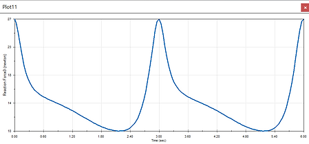
Force in Y of bearing
