I. Goal of the Project
The goal of this project is to create a skateboard design on CAD which will be studied under a stress simulation on Solidworks. The simulation should provide insights into how the design can be improved and what considerations need to be made when designing a skateboard. The analysis should prompt the selection of material along with the shape design of the skateboard.
II. Constraints
-
Supports up to 180 lbs and a shoe size of 12
-
Not more than 0.375 inch displacement of the skateboard when the load of the weight is put onto the board.
-
Safety factor of 3
III. Relevant Information
Because of how the constraints work in Solidworks, one of the constraints must be a pin and a roller so that the skateboard does not drift off freely. It should only be able to move in a direction parallel to the board. The shape of the board changes what purpose it is for, a longer board will change how the board will behave under deformation. The positioning of the wheels will also change how the board reacts to the load.
IV. Design Decisions and Model of the Deck
The basis for the design was how accurate it can be to an average skateboard. The length of the board is 34 inches. Originally the board was too long and the stress was loaded too far from the supports and the board would fail. The width of the board is enough to support a shoe size of 12, which I modeled as 8 inches wide. The ends of the board are not relevant when considering the load is placed in between the two supports, so I created rounded ends. I decided to place supports at the ends of the flat part of the skateboard before it curves upward. One of the constraints was modeled as a fixed geometry, while the other was a roller.
Figure 1: Image of the original constraints of the board
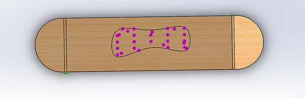
I modeled a sketch to be where the foot would be on the board. I made the assumption that all the load would be put onto one foot on the board at a time. The force was then distributed along this sketch.
Figure 2: Image of the sketch of the foot print
However, when modeling the constraints along the base of the board, the simulation would fail because of too much deformation. This most likely had to do with the height of the supports compared to the body. It would have been at the same height or slightly higher than the bottom of the skateboard. Because of this, I decided to model the actual wheels on the skateboard as rectangular extrusions.
Figure 3: Image of the wheel constraints
Two of the wheels were fixed and two were rollers.
V. FEA Simulation & Material Selection Process
Material 1: Balsa
The first material tested was Balsa wood. The yield strength is 2.0 *10^7 N/m2. The maximum strength was on one of the roller supports and it was 8.985 * 10^6 N/m2. This only has a factor of safety of 2.23 so it does not meet the constraint of the safety factor. The mass would be 1.52 pounds.
Figure 4: Image of the stress concentration of the skateboard made from Balsa wood.
It must also not deform more than 0.375 inches. This board would deform 0.72 inches when the load is put onto it so it also does not satisfy the deformation constraint.
Figure 5: Image of the Balsa board deformation distribution
Material 2: PPE
The second material that was tested was PPE, a plastic. According to matweb, the yield strength of PPE is 148 MPa. The maximum stress on the board is 9.55 MPa, so this does satisfy the factor of safety. The mass of the board would be 10.05 pounds according to the material properties.
Figure 6: Image of the PPE board stress concentration
The max deformation is 0.94 so it does not satisfy the deformation constraint. This material
therefore cannot be used.
Figure 7: Image of the displacement distribution on the PPE board
Material 3: Maple
For the maple material I had to manually insert the material properties. The maximum stress the board experiences is 9.44 MPa and the yield strength is 28.3 MPa. Therefore the factor is safety is exactly 3, which satisfies the stress constraint. This board would be 4.64 pounds.
Figure 8: Image of the stress concentration on the maple board.
The maximum displacement that the board experienced is 0.22 inches which is less than then 0.375 inches specified.
Figure 9: Image of the displacement distribution on the maple board
Given the stress and displacement on each material, Maple would be the best choice for the material of the board. It is also more lightweight than PPE while being more sturdy than balsa.
VI. Design Optimization
Some design optimizations that can be made in the future to minimize the weight is to change the ends of the board where there won’t be as much displacement. The ends can be thinner than the center of the board. Furthermore in an actual skateboard the wheels would not be made out of wood but rather probably some polymer that would be lighter. A smaller board would also probably be able to still support the load and probably actually support more load since the supports would be closer to the center of the board. So two design improvements if the weight is the primary concern would be changing the thickness of the board and the length.
VII. Conclusion
The goal of the project was successful in creating a skateboard design that satisfies the given constraints. By using simulated supports and loads several design optimizations were able to be made, including the type of material chosen and the positioning of the supports on the body of the skateboard. There were 3 materials tested: Balsa wood, PPE polymer, and Maple wood. The only material that satisfied all the constraints was the maple wood and it came out to be 4.64 pounds. This weight could be cut down with some future design optimizations such as changing the thickness, length, and shape of the board. However because the factor of safety was exactly 3 there would have to be precise changes to make sure that the maximum stress it undergoes does not increase.